SECTION 1A

HEATING AND VENTILATION


CONTENTS

General Description
Diagnosis
Heater Electrical Wiring
Heater Trouble Diagnosis
Insufficient Heating
Inadequate Removal Of Fog Or Ice
Too Warm In Car
Blower Inoperative
Miscellaneous

GENERAL DESCRIPTION

The base heater system is designed to provide heating, ventilation, windshield defrosting and on some cars, side window defogging. Ram air ventilation is provided on some cars by two (2) outboard vent valves installed in the plenum. These vent valves are controlled by push-pull controls mounted in the instrument panel within reach of the vehicle operator. When either of these valves are opened, air will enter the passenger compartment from the pressurized plenum and be directed to the floor of the vehicle.
The power-vent, heat, and defrost provisions of the base system are controlled within the heater module. The module itself is composed of two (2) components - a blower air inlet and a heater defroster. The blower air inlet is mounted to the front of cowl and the heater defroster assembly is mounted to the rear of cowl. A gasket is used between the two to prevent air, water and noise entrance into the passenger compartment.
Air distribution is through a heater outlet, defroster duet, and power-vent duet work and outlets.
The three modes of the base heater system (vent, heat, defrost) are controlled by the functional assemblies within the heater module. These assemblies are defined below:
1. Motor & Fan Assembly (Blower)
Provides and regulates air flow from the air inlet for further processing and/or distribution.
2. Heater Core
Transfers heat from engine coolant to inlet air, thus heating the inlet air.
3. Temperature Valve
Regulates the amount of air passing through the heater core, thus controlling the temperature and mix of heated and ambient air.
4. Mode (Defroster) Valve
Regulates the flow and distribution of processed air to the distribution (heater or defroster) ducts.
5. Vent Valve
Regulates the flow of non-processed (outside) air into the passenger compartment.
The operation of these assemblies is controlled by the levers and switch on the control head. Depending on model application, two (2) or three (3) indexed snap-in cables are attached to the module and control levers.
The temperature cable has the slider-type, self-adjust feature. As the temperature lever of the control head is cycled through its full range of travel, the cable clip will assume a position assuring that the temperature valve will seat in both extreme positions. The vent and/or defrost cables also have the self-adjusting feature. Blower speeds (OFF - LO - MED. - HI) are controllable in all modes (VENT, HEAT, DEFROST) by the switch on the control head.
The power-vent ventilation feature is available in the vent mode. Outside air enters the plenum and is driven by the blower to the temperature valve. In the cold position of the temperature valve, air bypasses the heater core to the vent valve opening and enters the passenger compartment through the vent duct and outlets in the center of the instrument panel. If some heated air is desired, the temperature valve may be opened. This allows mixed (tempered) air to flow out the center vent opening.
Blending air between modes can be done by varying the mode selector.
Varying the selector between "Heat" and "Defrost" will allow more air or less air to be directed Out either the defroster outlet or the heater outlet. The closer the mode selector is positioned to the "Heater" position, the larger the amount of air coming out the heater outlet. The closer the mode selector is positioned to "Defrost," the larger the amount of air going to the windshield. The temperature of this air is governed by the temperature lever position.
Side window defogging, if so equipped, is provided via ducts in the outboard corners of the instrument panel. Maximum air flow from these vents will be in "Heater" mode with reduced air flow in "Defrost" mode.
Varying the mode selector between "Heater" and "Vent" positions likewise varies the proportion of air coming out the heater outlet and the center vent outlets. With the selector in some midway position, air coming out the center vent outlets will be ambient temperature, while air out the heater outlet will be mixed warm air, its temperature depending on temperature lever position.
In the heat and defrost mode, outside air is driven by the blower to the temperature valve which, dependent upon its position as controlled by the operator, distributes all or some portion of the inlet air through the heater core. The vent valve will prevent air entry into the vent duct and direct this ambient air to the mix portion of the heater module. The air is thus heated, mixed, and then directed into either the defroster duct or the heater outlet by the position of the mode valve and control lever. A small amount of air is bled to the side window defogger system.

DIAGNOSIS

HEATER ELECTRICAL WIRING

The heater wiring diagrams are shown in Electrical Diagnosis, Section 8A, and should be referred to for diagnosis of electrical problems in the heater system.

1 Side window defog outlets*
2 Defroster outlets
3 Ram air vent outlets*
4 Power vent outlets
5 Power vent/heat outlets*
6 Ram air vent controls*
*Not on all models

Fig. 1A-1 Heated Ventilation System-Typical


1 This position allows outside air flow to the floor outlet. (additional vented air can be distributed inside car by operating vent knobs).
2 Position of this system selector lever determines air flow from floor, instrument panel or windshield outlet-in "heater," flow is about 80% to the floor and 20% to windshield outlets (and side window defoggers).
3 This position allows about 80% air flow to the windshield and 20% to the floor.
4 Temperature lever position will regulate outlet air temperature by blending the incoming outside air through/around the heater core.
5 The fan control lever (OFF - HI) provides speed control of the fan.

Fig. 1A-2 Heater Control-Typical


1 Front inlet
2 Rear body lock pillar exhaust valve
Fig. 1A-3 Interiour Body Air Flow & Exit-Typical


Fig. 1A-4 Interiour Body Air Flow & Exit-Typical Sedan, Station Wagon


Fig. 1A-5 Typical Heater System Air Flow


Fig. 1A-6 Heater Functional Test - Typical


HEATER TROUBLE DIAGNOSIS

INSUFFICIENT HEATING

Cause Correction
Slow warming in car. - Incorrect operation of controls. Advise operator of proper operation of heater controls. Explain operation of vents and controls.
- Low coolant level.
- Check control cable and blower operation.
Objectionable engine or exhaust fumes in car. - 
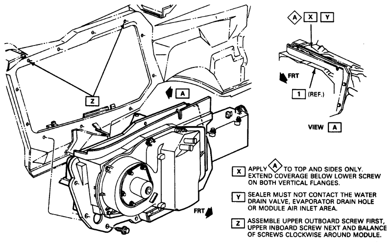
Check for seal between engine compartment and plenum.
- Check for proper sealing between air inlet duct assembly and cowl.
- Locate and seal any other air leaks.
Cold drafts on floor. - Check operation and adjustment of vent cables.
- Advise operator of proper operation of heater system.
- Advise operator to use blower to force air to rear seat area.
- Check to be sure front floor mat is under floor mat retainer at cowl
Insufficient heat to rear seat. - Obstruction on floor, possibly wrinkled or torn insulator material between front seat and floor.
- Advise operator to use HI blower speed.
Low engine coolant level - drop in heater air temperature at all blower speeds. - Check radiator and cooling system for leaks, correct and fl11 to proper level. Run engine to dear any air lock.
Failure of engine cooling system to warm up. - Check engine thermostat; replace if required.
- Check coolant level.
Kinked heater hoses. - Remove kink or replace hose.
Foreign material obstructing water flow through heater core. - Remove foreign material if possible, otherwise, replace core - can usually be heard as squishing noise in core.
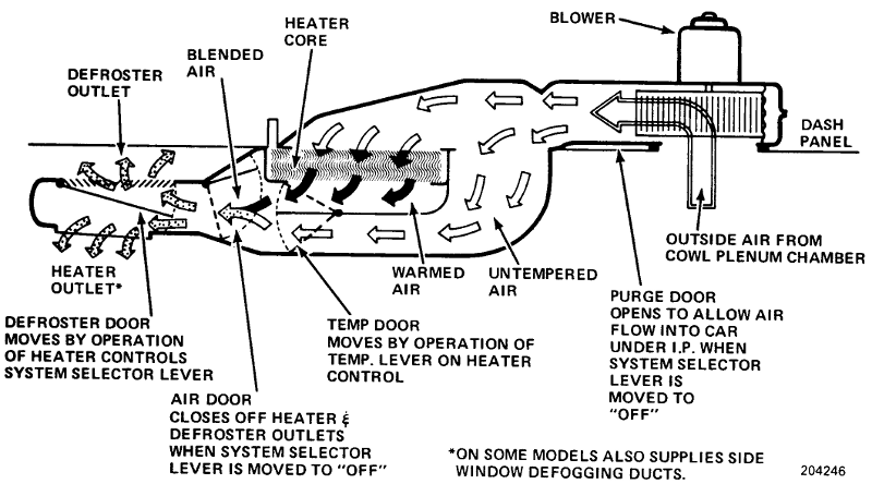
Temperature door valve) may be improperly adjusted.
Air doors do not operate.
- Check installation and/or adjustment of air control or air-defrost cable.

INADEQUATE REMOVAL OF FOG OR ICE

Cause Correction
Air door does not open.
Defroster door does not open fully.
- Check cable operation.
Air door does not open. - Check installation and/or adjustment of air control or air-defrost cable.
Temperature door does not open. - Check and adjust temperature control cable if necessary.
Obstructions in defroster outlets at windshield. - Remove obstruction.
- Look for and fix loose instrument panel pad cover at defroster outlet.
Damaged defroster outlets. - Reshape outlet flange with pliers.
- The outlet should have a uniform opening.
Blower motor not connected. - Connect wire. Check ground.
Inoperative blower motor. - 
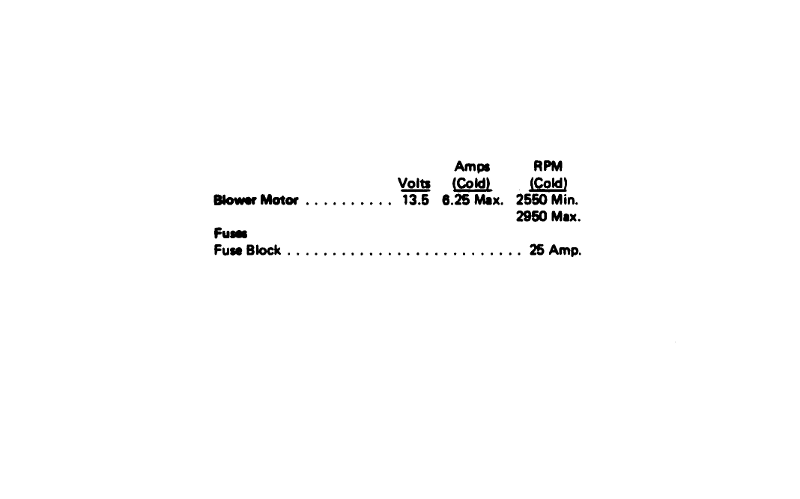
Check heater fuse and wiring. Replace motor if necessary.
Inoperative blower motor switch. - Replace switch if necessary.

TOO WARM IN CAR

Cause Correction
Temperature door improperly adjusted. - Adjust temperature cable.
Incorrect operation of controls. - Advise operator of proper operation of heater system.

BLOWER INOPERATIVE

Cause Correction
Blown fuse. - Replace fuse.
Open circuit. - Repair circuit between ignition switch, blower switch and blower motor.
Inoperative blower motor switch. - Replace faulty switch.
Shorted or open blower resistor. - Check blower motor resistor.
Inoperative motor. - Replace motor.

MISCELLANEOUS

Cause Correction
Blown fuses caused by short in electrical system. - Locate and correct short.
Open circuit. - Repair circuit between ignition switch, blower switch and blower motor.
Front floor mat wet under heater caused by improperly sealed windshield or leaking heater core. - Reseal windshield, or lead-in from radio antenna.
- Repair (if possible) or replace heater core.
- Check for proper seal to cowl and for leak at hose connection on heater core. Hose leaking into the heater case is often misdiagnosed as leaking core.
Heater "gurgle," whine or "swish." - Check engine coolant level in radiator.
- Check for obstruction in core and/or hoses.

ON CAR SERVICE

Fig. 1A-7 G Series Heater Interior Service Procedures 1 of 2

HEATER CONTROL CABLE ADJUSTMENTS

G And B Series Temperature Cable
    1. Place temp lever at full COLD position (full left).
    2. Rotate temp door crank to full COLD position (crank rotated full clockwise as viewed from above).
    3. Adjust turnbuckle until cable loop lines up with pin on crank.
    4. Move lever to full HOT. If door is not heard hitting its seat, repeat the adjustment procedure.

B Series Shut-Off Valve (Purge Door) Cable
    1. Rotate bell crank to pull valve (door) closed against module case.
    2. Adjust turnbuckle to enable.
    3. Installation of cable end to bell crank post and snap in flag.

Fig. 1A-8 G Series Heater Interior Service Procedures 2 of 2

Fig. 1A-9 G Series Heater Module Service Procedures 1 of 2

Fig. 1A-10 G Series Heater Module Service Procedures 2 of 2

Fig. 1A-11 B Series Heater Service Procedures 1 of 3

Fig. 1A-12 B Series Heater Service Procedures 2 of 3

Fig. 1A-13 B Series Heater Service Procedures 3 of 3

Fig. 1A-14 Heater Hose Routing - B Series

Fig. 1A-15 B Series Heater Service Procedures 3 of 3